
Green Energy and Sustainability ISSN 2771-1641
Green Energy and Sustainability 2026;6(1):0003 | https://doi.org/10.47248/ges2606010003
Original Research Open Access
Simulation of heat transfer in a large-scale flat plate collector
Yusuf Karakaş
1,2

 ,
Tuba Okutucu-Özyurt
3,†
,
Rosie Christodoulaki
4,†
,
Harry Michalopoulos
5
,
Sevan Karabetoğlu
3
,
Vasiliki Drosou
4
,
Tuba Okutucu-Özyurt
3,†
,
Rosie Christodoulaki
4,†
,
Harry Michalopoulos
5
,
Sevan Karabetoğlu
3
,
Vasiliki Drosou
4
Correspondence: Yusuf Karakaş
Academic Editor(s): Tony Roskilly, Georgios Martinopoulos, Georgia Kastrinaki, Hande Eryilmaz, Martin Roeb
Received: Oct 2, 2025 | Accepted: Jan 27, 2026 | Published: Feb 18, 2026
This article belongs to the Special Issue Selected Papers from the Conference ICRES 2025
© 2026 by the author(s). This is an Open Access article distributed under the Creative Commons License Attribution 4.0 International (CC BY 4.0) license, which permits unrestricted use, distribution and reproduction in any medium or format, provided the original work is correctly credited.
Cite this article: Karakaş Y, Okutucu-Özyurt T, Christodoulaki R, Michalopoulos H, Karabetoğlu S, Drosou V. Simulation of heat transfer in a large-scale flat plate collector. Green Energy Sustain. 2026;6(1):0003. https://doi.org/10.47248/ges2606010003
Solar thermal energy plays a vital role in the transition toward sustainable and energy-efficient heating solutions. Among the available technologies, flat plate collectors (FPCs) remain one of the most widely adopted systems for low-temperature applications (≤120℃), including residential water heating, industrial process heat, and district heating. Enhancing the thermal performance of large-scale FPCs is essential to improve efficiency, reduce energy losses, and ensure adaptability across diverse climatic conditions. This study presents a computational fluid dynamics (CFD) thermo-hydraulic analysis of riser tubes in a large-scale flat plate collector (FPC) using ANSYS Fluent. Three riser lengths (4.45 m, 5.45 m and 6.45 m) are examined with regard to temperature distribution, hydraulic behavior, and energy and exergy performance. An aqueous solution of 50% (w/w) glycol enters the risers at 15 °C with a velocity of 0.4 m/s, while non-uniform heat fluxes of 750 and 100 W/m2 are considered on the sun-facing and shaded sides. For riser lengths of 4.45 m, 5.45 m and 6.45 m, the CFD simulations indicate outlet temperatures of 89.63 °C, 96.81 °C and 103.61 °C, corresponding to thermal efficiencies of 74.1%, 77.0% and 79.4% and exergy efficiencies of 8.0%, 9.6% and 11.1%, respectively. Fully developed laminar flow is observed, with pressure drops (2.7–3.56 kPa) and low pumping power demands. To ensure numerical reliability, a mesh-independence study was carried out for the 5.45 m riser. Refining the grid from 6.5 × 10⁵ to 7.43 × 10⁵ cells changed the outlet temperature by less than 0.2%; therefore, Mesh 2 was adopted for all simulations. Taken together, the mesh-independence analysis and the comparison with monitoring data support the reliability of the numerical model. Overall, the longest riser provides the highest energy and exergy performance but operates close to the stagnation temperature range (100–120 °C), reducing safety margins. The intermediate 5.45 m riser emerges as the most balanced configuration, combining high thermal and exergy efficiencies with more moderate outlet temperatures and hydraulic losses; it is therefore recommended for real-world deployment in large-scale FPC systems.
KeywordsSolar thermal energy, flat plate collectors, low temperature solar heat, CFD
Solar thermal energy is widely used in applications ranging from residential water heating to large-scale industrial processes. Among the various available technologies, large-scale flat plate collectors (FPCs) are widely adopted due to their cost-effectiveness, reliability, and ability to produce low-temperature heat. However, maximizing their thermal performance remains a challenge, as factors such as heat losses, design limitations, and material selection play a crucial role in overall efficiency. In particular, large-scale FPCs are employed in district heating, industrial process heat, and commercial water heating systems. However, optimizing their thermal performance remains a complex challenge [1-4].
Recent advancements in materials and manufacturing techniques have improved heat absorption and retention, enhancing the performance of large-scale FPCs. Innovative designs, including advanced surface coatings and optimized flow patterns, further enhance efficiency and support long-term viability. The performance of a large-scale FPC largely depends on two key components: the absorber plate and the riser tubes. The absorber plate, typically made of high thermal conductivity materials like copper or aluminum, is coated with selective coatings to maximize solar energy absorption. Meanwhile, the riser tubes, which transport the working fluid, are critical to efficient heat transfer [3,5-8]. Their thermal properties, diameter, arrangement, and length directly influence the collector’s overall performance. Beyond material selection, the way the absorber plate is bonded to the riser tubes significantly affects heat conduction. Proper insulation around the collector is also essential to minimize heat loss and improve efficiency. Additionally, optimizing the choice of working fluid and its flow rate ensures better heat transfer and overall system stability [4,9].
Heat loss coefficients, thermal capacity and efficiency are common indicators used to evaluate the thermal performance of large-scale FPCs. Thermal efficiency quantifies how well absorbed solar energy is converted into usable thermal energy. Conduction, convection, and radiation from the absorber plate and the transparent cover are the main ways of heat losses. Minimizing these losses is crucial for enhancing the overall efficiency of the collector [5]. Toapanta et al. (2020) evaluated the thermal performance of three different FPC models with varying cross-sectional shapes. The collector with Type I cross-section exceeded Type II and III models, achieving the highest outlet temperature and an efficiency of 68% when CFD analysis was conducted using ANSYS Fluent. In addition, the Type I model demonstrated reduced fluid velocity and pressure drop, indicating its improved performance. The study highlights the significant impact of cross-sectional geometry on the overall efficiency of solar collectors [4]. Badiei et al. (2020) developed a fully transient 3D CFD model of an FPC integrated with a PCM layer and fins, solving the full momentum and energy equations in all components and accounting for realistic, time-varying ambient conditions. Their results showed that a PCM with a melting point near 35–40 °C can increase average daily efficiency from approximately 33% (no PCM) to about 46%, while significantly extending the duration of hot-water availability into the evening. Higher-melting PCMs and fin configurations are more sensitive to climatic conditions, highlighting the importance of matching PCM properties and geometry to the target application [2]. Using CFD analysis and CAD modeling, Junaid et al. (2017) presented a thermal performance analysis of an FPCs. Throughout the month of March, the solar collector was replicated at various times of the day. Each time slot's fluid temperature and collector efficiency were compared for the study, with 12 PM showing the highest temperature and efficiency. The effect of solar radiation caused a 15.89 °C increase in fluid temperature [6]. Alkhafaji et al. (2024) investigated methods to improve the thermal performance of FPCs by analyzing four models using passive techniques under transient solar radiation. Models A and B focused on riser-pipe configurations with semicircular and elliptical cross-sections, while models C and D analyzed plate geometries with dimples and channels. Simulations conducted with ANSYS 19. (R3) showed all models surpassed the traditional design in thermal response and efficiency. Model D performed the best, achieving a 13.2% higher working fluid temperature and 13.7% higher overall efficiency due to increased heat transfer [7]. Freegah et al. (2024) employed both numerical and experimental methods to examine and compare the thermal responses of a newly designed FPC with a conventional one. The new model increases the surface area exposed to solar radiation by adding wavy fins and elliptical riser pipes. The new model performs better than the conventional one, as demonstrated by ANSYS Fluent simulations, which show increments in mass flow rate of 7.9% and overall thermal efficiency of 22.4%. The investigation concludes that the experimental and numerical results agree well, emphasizing the new design's significant increase in thermal capacity [8]. Wang et al. (2022) investigated large-scale FPCs and found that although increasing the collector dimensions greatly enhances thermal efficiency, the benefits start to decrease beyond a certain size. Their study also showed that regional and climatic factors, such as low solar irradiance and cooler ambient temperatures, can make large-scale FPCs particularly effective in sun-abundant regions like the Tibetan Plateau [9]. Facão (2015) highlighted the importance of uniform flow distribution, demonstrating that optimizing header geometries can reduce flow variation and enhance heat conversion [10]. Similarly, Jiandong et al. (2015) and Hung et al. (2017) examined structural parameters, such as absorber plate thickness, tube spacing, and diameter, and found that these adjustments increase efficiency and lower heat loss. Computational fluid dynamics (CFD) simulations further validated these design improvements. Innovative concepts have also emerged [11,12]. Xia et al. (2023) introduced porous metal blocks on the absorber walls, leading to a marked improvement in heat transfer coefficients and boosting performance evaluation criteria by up to 80% compared to conventional designs [13]. Gao et al. (2023) proposed an evacuated FPC for direct steam generation, demonstrating a 10% efficiency improvement over pressurized water systems and effectively addressing seasonal mismatches in solar energy availability [14]. Nedunchezhiyan et al. (2025) investigated the thermal and fluid dynamics of a hybrid solar water heating system combining evacuated tube collectors (ETCs) and FPCs using ANSYS Fluent. The analysis of varying flow rates (1–10 lpm) showed that lower flow rates (1 lpm and 4 lpm) enhanced heat transfer efficiency, achieving peak outlet temperatures of 87.56 °C and 84.57 °C. Pressure distribution increased linearly with flow rate, while higher flow rates led to greater turbulent kinetic energy (TKE). The study emphasized the benefits of integrating FPCs and ETCs for improved efficiency under diverse conditions and demonstrated CFD’s role in optimizing system design [15]. Shivanayak et al. (2025) investigated an FPC equipped with wavy riser tubes combined with coil inserts of 10, 20, and 30 mm pitch over a turbulent Reynolds number range of 5500–14,500. Experiments and CFD simulations showed that the interaction between the wavy geometry and coil turbulators strengthens secondary flows, increases residence time, and disrupts the thermal boundary layer. Compared to plain tubes, the Nusselt number increased by roughly 15–35% for a 30 mm pitch and 41–49% for a 10 mm pitch, depending on Reynolds number. The collector efficiency reached about 84% at Re = 14,500 for the 10 mm pitch [16]. Thakur et al. (2021) reported that metal-oxide nanofluids (CuO, Al2O3) consistently outperform water in terms of heat transfer coefficient and collector efficiency, with CuO–water nanofluids yielding up to ~22% efficiency gains over water. Propylene-glycol/water mixtures at optimized concentrations offer improved efficiency and freeze protection, and graphene-based nanofluids are highlighted as promising future options [17]. Zheng et al. (2024) developed a high-performance flat plate collector by combining plastic transparent insulation material (TIM) with a 2 cm silica-aerogel layer in the cover, optimized using a fast 1D NEST-based energetic/exergetic model. Prototype tests showed energy efficiency up to ~55% and exergy efficiency ~8%, with 10–50% higher energetic performance than previous TIM-only prototypes and commercial collectors in the high-temperature regime [18]. Pandey and Chaurasiya (2017) presented a broad review of analysis and development strategies for solar flat plate collectors, covering nanofluids, modified absorber plate designs, heat-loss reduction methods, polymer collectors, mini/micro-channels, PCMs, reflectors, and inserts. They emphasize the complementary role of experiments, analytical models, and especially CFD in evaluating dynamic thermal behavior, optimizing design, and reducing the need for costly prototypes [19].
Unterberger et al. (2021) developed an adaptive forecasting approach for large-scale FPCs. By adjusting to seasonal changes, their method significantly improved accuracy, enabling better management of solar heat production [20]. Meanwhile, Li et al. (2022) examined a hybrid approach that combined large-scale FPCs with heat pumps, achieving notable energy savings and CO2 emission reductions. Their work offers a practical solution for rural heating in cold climates [21]. Sharafeldin et al. (2025) examined pulsating flow as a method to enhance FPC thermal performance. Using a solenoid valve to create pulsations, they found that lower frequencies improved thermal efficiency by up to 22.8%, while also enhancing the heat removal factor and reducing collector size [22]. Amraoui et al. (2024) investigated various baffle configurations through CFD simulations. The maze-like design stood out, significantly increasing turbulence, and achieving a 40% higher Nusselt number than other configurations. Both approaches provide cost-effective advancements for improving FPC efficiency and sustainability. However, challenges remain, including the precise representation of boundary conditions, mesh generation for complex geometries, and validation of simulation results against experimental data. Addressing these issues is essential for the effective optimization of solar collectors using CFD [23].
Recent studies have employed CFD tools, especially ANSYS Fluent, to simulate and optimize heat transfer in FPCs. These tools provide high-resolution insights into temperature distributions, flow velocities, pressure drops, and thermal gradients, allowing researchers to test design configurations without the need for extensive physical prototyping.
This paper presents a comprehensive CFD-based thermal analysis of the riser tubes in a large-scale flat plate collector (FPC). Three riser lengths (4.45 m, 5.45 m and 6.45 m) are investigated to assess their influence on overall thermal performance and to identify the most effective configuration. The temperature distribution within the collector is simulated using ANSYS Fluent to gain deeper insight into the governing heat-transfer mechanisms and potential performance improvements. Beyond temperature fields, the study also examines velocity profiles, frictional pressure losses, pumping power requirements, and associated stagnation risks. These results are complemented by a mesh-independence assessment and verification of the predicted outlet temperatures against measured operating and stagnation ranges. By combining thermal and hydraulic indicators, the analysis provides a solid framework for selecting an optimal riser length for real deployment in large-scale FPC systems.
The simulation framework involved geometric modeling, mesh generation, boundary condition definition, and solver configuration using ANSYS Fluent. All riser models were evaluated under the same boundary conditions to enable a direct comparison.
Three models were created in SolidWorks, each with riser lengths of 4.45 m, 5.45 m, and 6.45 m, respectively. The risers had circular cross-sections with a diameter of 8 mm. In contrast, the headers featured a larger diameter of 35 mm to facilitate proper flow distribution. To simulate realistic inlet and outlet conditions, each model incorporated upper and lower headers. An image of the large-scale FPC is shown in Figure 1, while Figure 2 presents the detailed geometry of the corresponding risers and headers used in the CFD model.

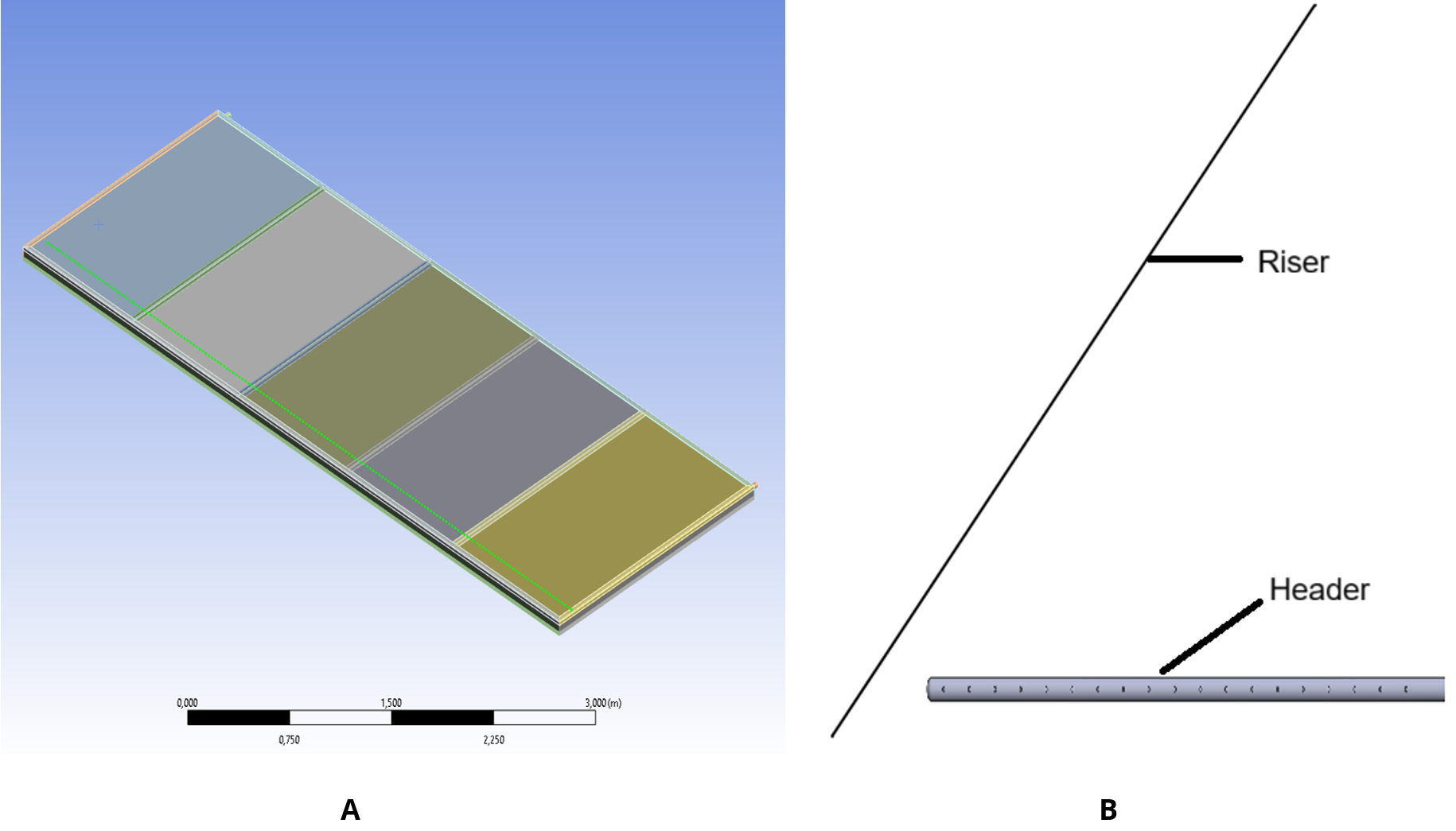
Figure 1. Overview of the large-scale FPC system showing the large-scale unit (A) and a close-up view of the riser tubes and header section (B).
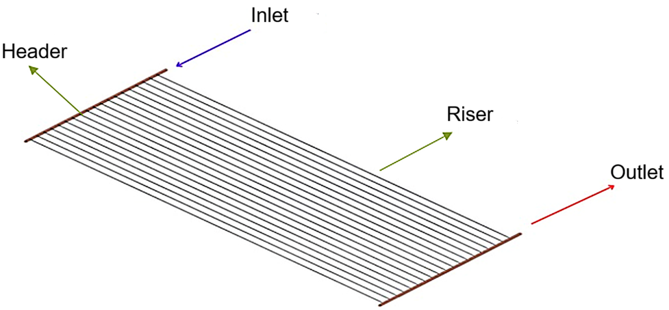
Figure 2. Geometric model of the risers and headers.
The geometries were imported into ANSYS Meshing for grid generation. A tetrahedral mesh was used, with inflation layers added near the wall regions to accurately resolve velocity and temperature gradients. Mesh independence studies were carried out for each configuration, confirming numerical stability with an average element size of 5 mm. The meshing approach and structure for the riser are illustrated in Figure 3.
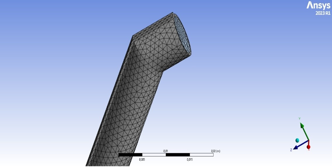
Figure 3. Meshing structure for the riser.
To verify that the numerical results were not sensitive to mesh resolution, a mesh independence study was carried out for the 5.45 m riser as a representative case. Three meshes were generated by progressively refining the grid while keeping the boundary conditions unchanged. For each mesh, steady-state simulations were performed, and the outlet temperature was monitored as the primary indicator of solution accuracy.
As summarized in Table 1, increasing the mesh from the Mesh 2 to Mesh 3 level altered the riser outlet temperature by less than 0.2%. This confirms that further mesh refinement has a negligible effect on the solution. Consequently, the Mesh 2 was adopted for all subsequent simulations as an appropriate compromise between accuracy and computational cost.
Table 1. Results of the mesh independence study for the 5.45 m riser.

The simulations were performed under steady-state conditions. A uniform inlet flow velocity of 0.4 m/s was applied, using a 50% glycol–50% water mixture at an inlet temperature of 15 °C as the working fluid. Heat flux boundary conditions were imposed on the outer surfaces of the riser tubes: 750 W/m2 on the sun-facing side and 100 W/m2 on the shaded side. The tube walls were modeled as thermally conductive copper, and conjugate heat transfer (CHT) was enabled to account for heat conduction within the solid and convective transfer in the fluid. Atmospheric pressure was specified at the outlet, while all wall surfaces were assigned a no-slip boundary condition. The computational domain consisted of three main boundaries: the inlet, the outlet, and the wall surfaces. An illustration of the computational domain for the riser is presented in Figure 4.
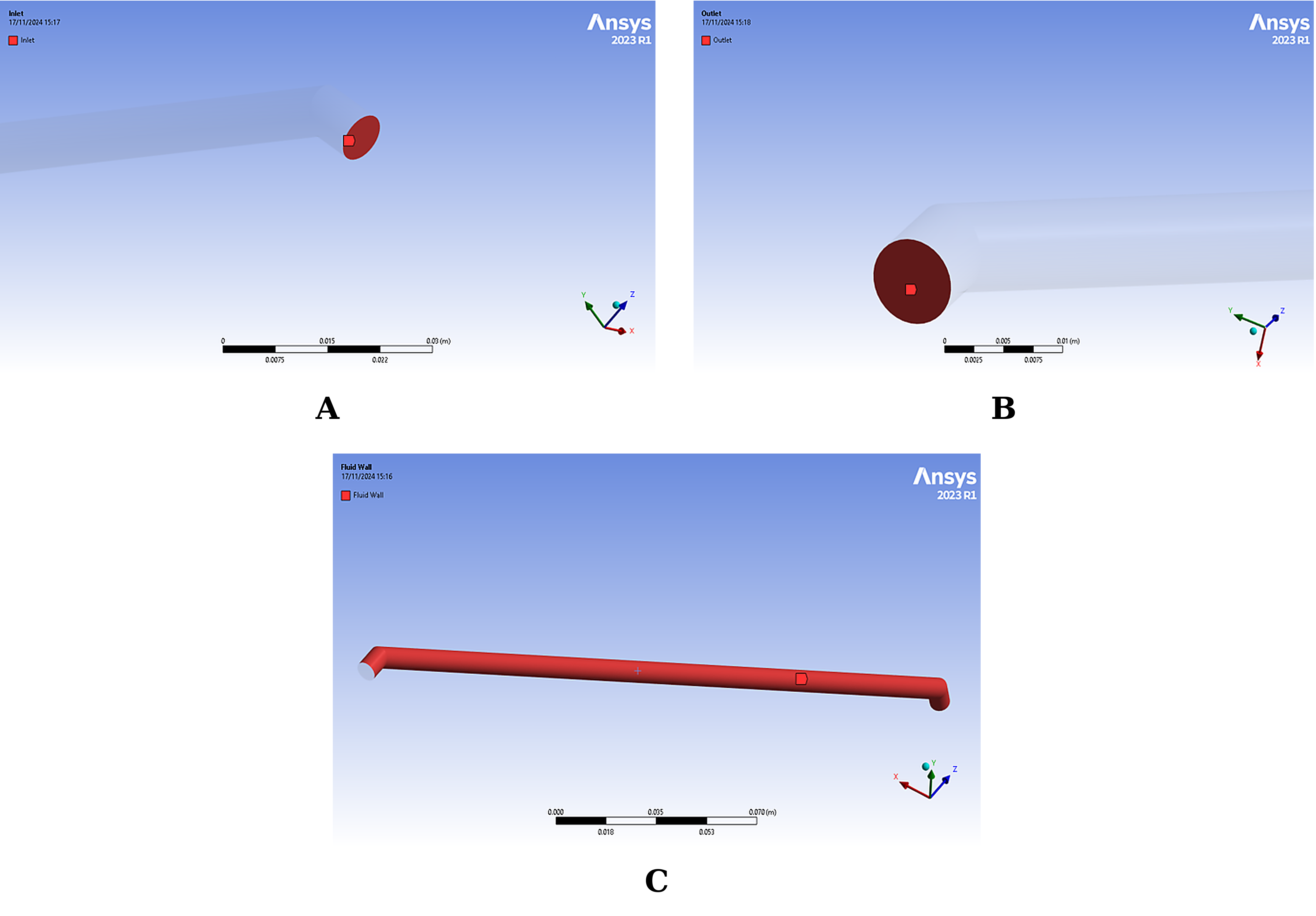
Figure 4. Domains and Boundary Conditions of the Riser. A: Inlet, B: Outlet, and C: Riser Wall.
In the real collector, the riser tubes are soldered to a flat absorber plate located beneath a transparent cover, and the entire assembly is subject to optical and thermal losses due to reflection, convection, radiation and conduction [24]. In the present CFD model, these loss mechanisms are not resolved explicitly. Instead, their combined effect is represented through prescribed heat flux boundary conditions of 750 W/m2 on the sun-facing side (corresponding to an overall loss of about 21% for an incident irradiation of 950 W/m2) and 100 W/m2 on the shaded side of the riser due to radiative exchange. These values are taken to represent the net heat transferred from the absorber plate to the tube wall under typical operating conditions, i.e. after accounting for top, bottom and edge losses at the collector level.
Because the risers are heated along their length, buoyancy is expected to influence the flow to some degree. Therefore, gravitational acceleration was explicitly included in the simulations as g=-9.81 m/s2 in the vertical direction, aligned with the riser axis. Buoyancy effects in the fluid were modeled using the Boussinesq approximation.
ANSYS Fluent's pressure-based solver was utilized, employing the realizable k–ε turbulence model for solving the momentum equations, along with the energy equation to account for thermal effects. All governing equations were discretized using second-order schemes to ensure higher accuracy. Convergence was considered achieved once the residuals for energy, momentum, and continuity equations fell below their respective thresholds.
The simulations were performed in ANSYS Fluent using a steady-state, pressure-based solver. Pressure–velocity coupling was handled with the SIMPLE algorithm, and pressure was discretized with a second-order scheme [25]. The momentum and energy equations were both solved using second-order upwind discretization to reduce numerical diffusion and improve the accuracy of the predicted velocity and temperature fields. Spatial gradients were evaluated with the Green–Gauss cell-based method.
Convergence was monitored using both residuals and integral quantities. In all cases, the scaled residuals were reduced below 10-4 for continuity and momentum, and below 10-6 for the energy equation. In addition, the outlet temperature and pressure drop were tracked to ensure that they had reached steady values before the solution was accepted as converged.
The working fluid, a 50% glycol–50% water mixture, was modeled as a temperature-dependent. Density, dynamic viscosity, thermal conductivity, and specific heat capacity were defined as functions of temperature for glycol–water mixture representative properties at 15 °C are given in Table 2 [26]. These properties were implemented in Fluent as temperature-dependent polynomials, allowing the local Reynolds and Prandtl numbers to be represented more realistically along the riser and leading to more accurate predictions of both heat transfer and pressure losses.
Table 2. Representative thermophysical properties of a 50% glycol–50% water mixture at 15 °C.
Near the walls, inflation layers were used to resolve the boundary layer. The first cell height was selected so that the non-dimensional wall distance y+ of the first node typically lay in the range 30–80, with an average value of about 45. This range is suitable for the realizable k–ε turbulence model with standard wall functions and ensures that the near-wall region is treated consistently with the chosen turbulence modeling approach [25].
This section evaluates the thermal and flow performance of riser tubes with different lengths under steady-state conditions. The analysis focuses on temperature distribution and velocity contours to assess heat absorption performance and flow behavior. As riser length increases, significant differences are observed in outlet temperatures and flow characteristics. Shorter risers exhibit steeper temperature gradients and more uniform flow profiles, indicating efficient convective heat transfer. In contrast, longer risers approach thermal saturation and show signs of reduced convective effectiveness.
Section 3.1 focuses on the axial temperature distribution and the resulting outlet temperature for each configuration, while Section 3.2 examines the corresponding velocity profiles at the riser outlet as indicators of flow uniformity, viscous resistance, and pumping requirements. Together, these results provide a combined thermo-hydraulic basis for assessing the suitability of each riser length in large-scale FPC applications.
The analysis focuses on temperature distribution and velocity contours to assess heat absorption performance and flow behavior. As riser length increases, significant differences are observed in outlet temperature and flow characteristics. Shorter risers exhibit steeper temperature gradients and more uniform flow profiles, indicating efficient convective heat transfer. In contrast, longer risers approach thermal saturation and show signs of reduced convective effectiveness. The evolution of velocity profiles with length also affects pressure losses and flow uniformity. These results highlight the tradeoffs between thermal and hydraulic performance in the design of large-scale FPCs.
The temperature distribution within each riser tube exhibited a distinct gradient from inlet to outlet, shaped primarily by the applied surface heat flux and the total riser length. As riser length increased, outlet temperatures rose accordingly, highlighting the combined influence of residence time and available heat transfer surface area on thermal performance.
For the shortest riser (4.45 m), the fluid temperature increased from 15 °C to 89.63 °C (Figure 5). The steep temperature gradient along the tube indicated efficient convective heat transfer and minimal thermal losses. Due to the short residence time, the heat transfer fluid (HTF) experienced limited energy accumulation, resulting in a lower outlet temperature. Such a configuration is well-suited for systems requiring lower outlet temperatures or high-throughput operation, where rapid and stable heat exchange is essential.
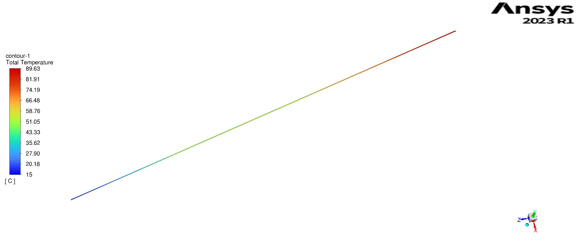
Figure 5. Temperature distribution along the 4.45 m riser.
In the intermediate case (5.45 m), the outlet temperature reached 96.8 °C (Figure 6). The gradient was more moderate, suggesting a balanced trade-off between thermal gain and convective efficiency. The increased residence time enabled more effective energy absorption while maintaining stable flow behavior. Although the thermal driving force naturally declined near the outlet, overall convective performance remained sufficient. Stratification risks in this configuration can be effectively mitigated through proper flow control, making this riser length a practical choice for large-scale solar thermal systems seeking a balance between efficiency and operational safety.
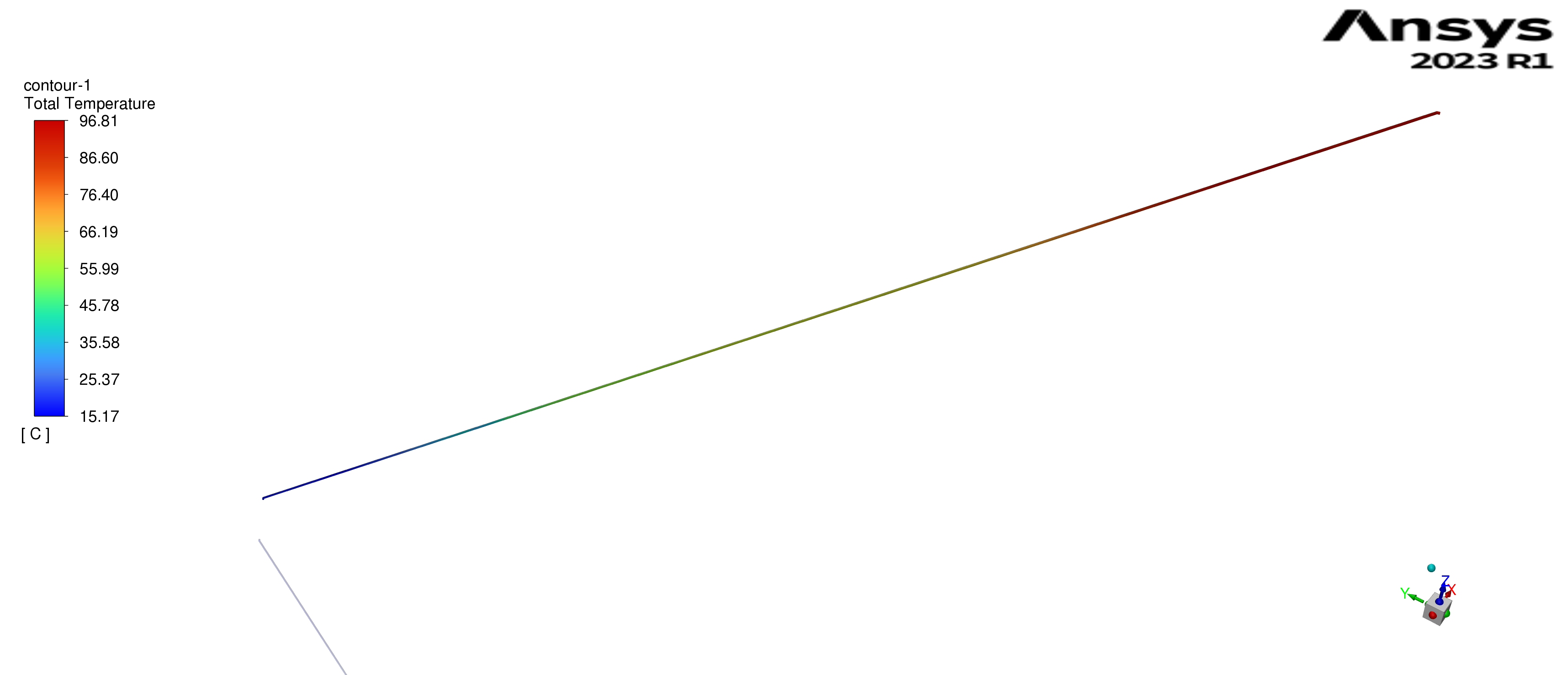
Figure 6. Temperature distribution along the 5.45 m riser.
The longest riser (6.45 m) yielded the highest outlet temperature of 103.61 °C, indicating maximum thermal energy gain (Figure 7). However, this also brought the system close to stagnation conditions. Stagnation temperature defined as the maximum temperature the fluid reaches when flow is interrupted, such as during pump failure poses a significant risk to system integrity. According to ISO 9806 and Duffie & Beckman (2013), the critical stagnation range for water-based systems lies between 100 °C and 120 °C [27]. The outlet temperature in the 6.45 m riser falls within this sensitive range, raising concerns over vapor formation, increased material stress, and reduced long-term reliability under off-nominal conditions. Additionally, the temperature gradient flattens near the outlet, signaling a reduction in convective effectiveness due to a weakened thermal driving force. The extended residence time further amplifies the system’s sensitivity to flow disturbances and increases the potential for thermal stratification. ISO 9806 type tests and manufacturer data for the large-scale FPC report stagnation temperatures between 100 °C and 120 °C for water-based operation [27]. Using these measured values as a reference, the 6.45 m riser can be considered to operate within the stagnation band, which raises concerns about vapor formation, increased material stress, and reduced safety margins under off-nominal conditions such as pump failure.
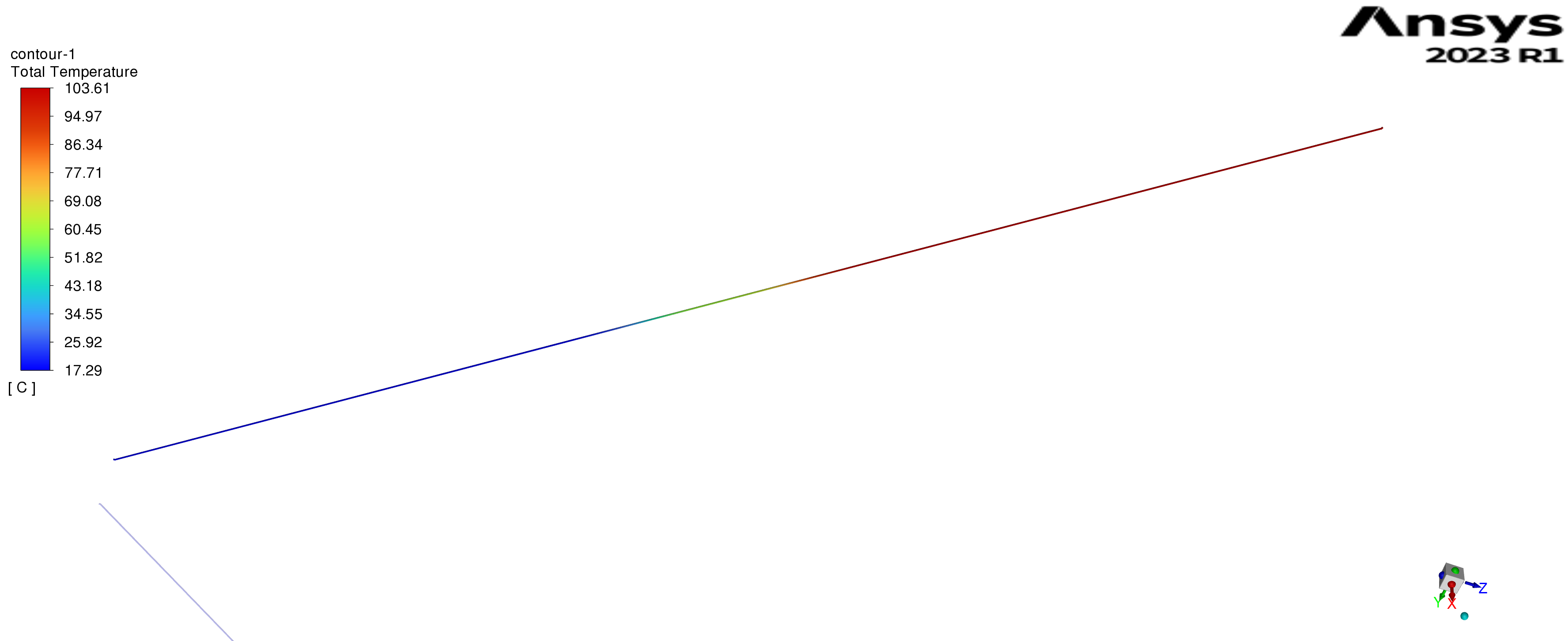
Figure 7. Temperature distribution along the 6.45 m riser.
Overall, the analysis of temperature distribution across the different riser lengths reveals clear trade-offs between thermal efficiency and system stability. Shorter risers enhance convective performance and mitigate thermal risks, while longer risers maximize energy absorption but require more sophisticated control strategies to prevent stagnation and ensure safe operation under varying conditions.
While Section 3.1 examined the thermal response of the different riser lengths, this section turns to the flow behavior, as velocity distribution and viscous resistance are key drivers of pressure drop, pump sizing and overall system stability. The outlet velocity profiles for all three riser configurations are predominantly parabolic, consistent with fully developed laminar flow. Nonetheless, changes in riser length introduce subtle but important differences that influence both thermal performance and hydraulic losses.
For the 4.45 m riser, the peak outlet velocity is approximately 0.53 m/s (Figure 8). The velocity profile retains a classic parabolic shape, indicating well-developed and uniform axial flow. Owing to the shorter flow path, frictional resistance is the lowest among the three cases, giving a frictional pressure drop of about 2.7 kPa per riser and a corresponding pumping power of roughly 0.054 W at the reference operating point. This configuration is therefore attractive in applications where high throughput and low electrical power consumption of the pump are prioritized.
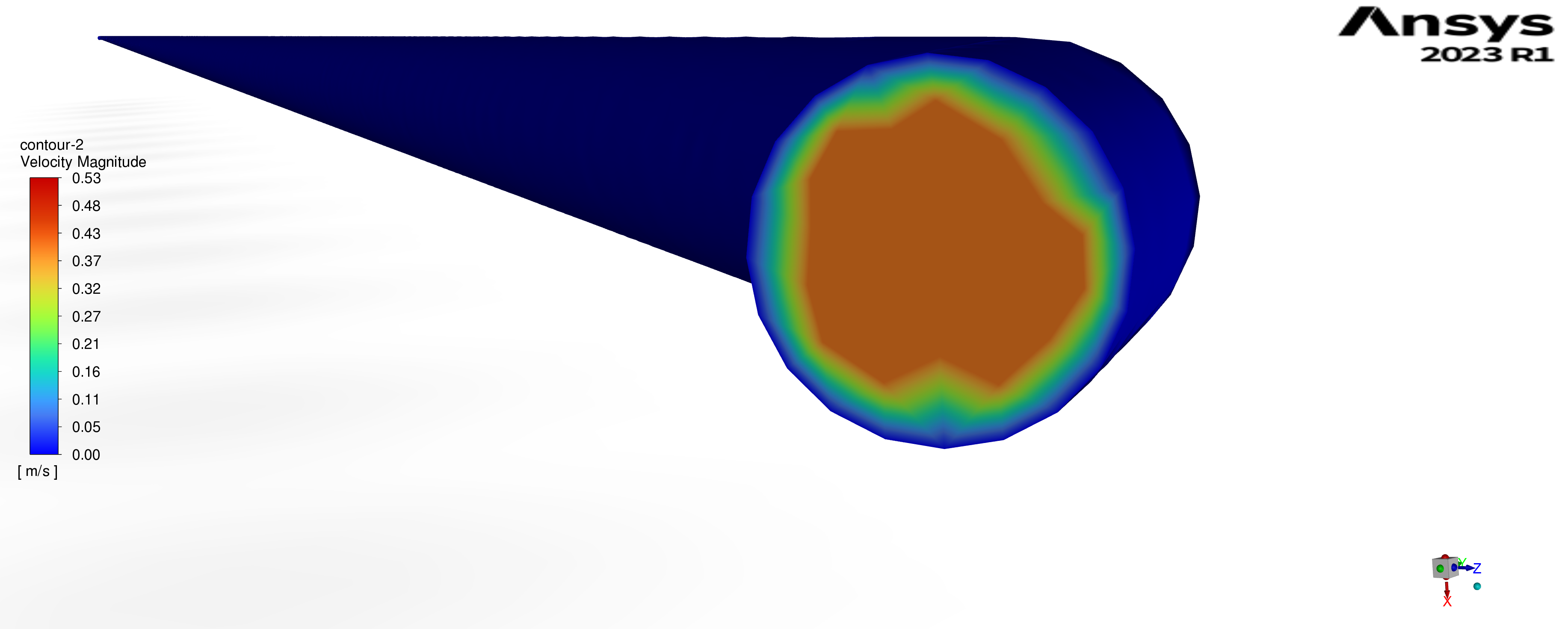
Figure 8. Velocity distribution at the outlet of the 4.45 m riser.
The 5.45 m riser exhibits a slightly higher peak velocity of around 0.605 m/s (Figure 9). Its velocity profile is flatter than that of the 4.45 m case, likely due to the longer residence time and stronger interaction with the heated wall. Despite this, the flow remains stable and fully developed. The increased length raises viscous resistance, resulting in a pressure drop of about 3.3 kPa and a pumping power of approximately 0.066 W per riser. This arrangement preserves good flow uniformity while the longer residence time supports enhanced heat transfer, making it a strong compromise between energy capture and hydraulic penalties.
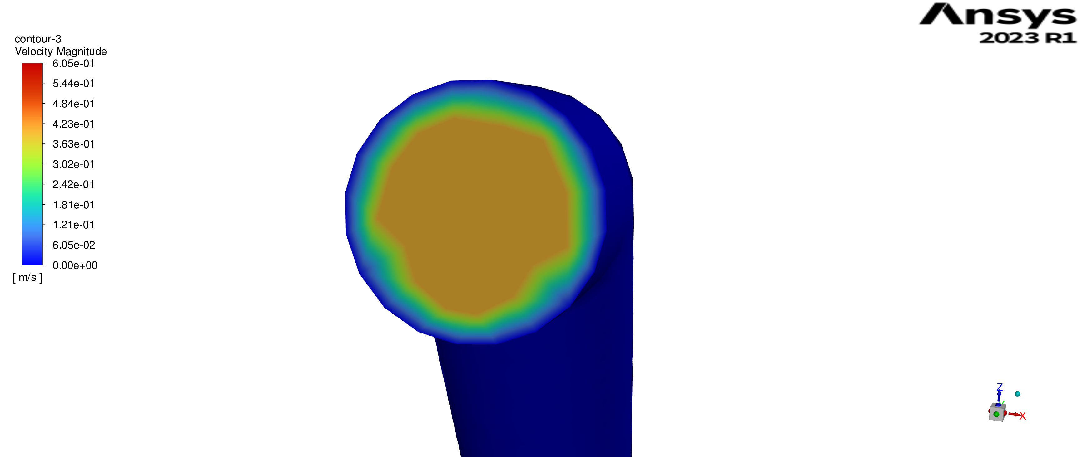
Figure 9. Velocity distribution at the outlet of the 5.45 m riser.
In the 6.45 m riser, the peak velocity increases only slightly to about 0.61 m/s, but the profile shows more pronounced decay near the tube walls (Figure 10). This additional flattening and peripheral damping indicate higher viscous resistance along the extended wetted surface. As a result, the frictional pressure drop increases to roughly 3.56 kPa, with an associated pumping power of about 0.076 W per riser. These higher losses suggest that, although the 6.45 m riser improves the outlet temperature, it does so at the expense of greater pumping demands and a narrower hydraulic safety margin.
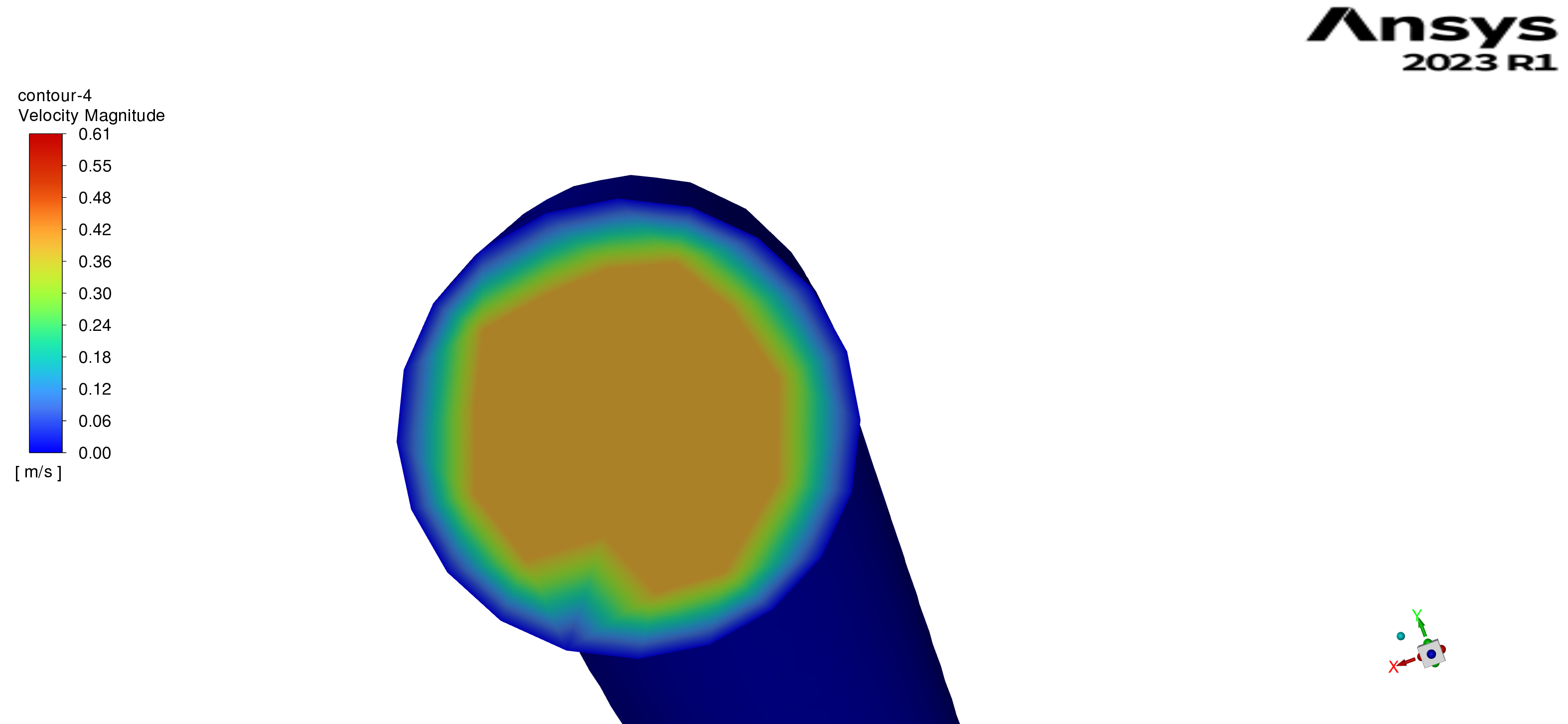
Figure 10. Velocity distribution at the outlet of the 6.45 m riser.
Overall, all three riser lengths maintain essentially parabolic, fully developed laminar profiles. However, the 5.45 m riser offers the most favorable combination of velocity distribution, pressure loss, and pumping power. It provides better thermal performance than the 4.45 m case while avoiding the relatively high pressure drop of the 6.45 m configuration, making it a promising choice for stable and energy-efficient operation in large-scale FPCs. A summary of the pressure losses and pumping powers per riser at the design operating point is given in Table 3.
Table 3. Pressure drop and pumping power per riser for varying riser lengths.
The numerical model was verified to ensure that the results were not influenced by discretization errors. Mesh quality was assessed through the mesh-independence study described in Section 2.2.1, where three different meshes were tested for the 5.45 m riser. As summarized in Table 1, increasing the resolution from Mesh 2 to Mesh 3 changed the riser outlet temperature by less than 0.2%, indicating that further refinement has a negligible impact on the solution. Mesh sensitivity levels of this order typically below about 1% variation in key thermal quantities are generally considered acceptable in CFD studies of internal flows and heat-transfer systems [28,29].
Convergence was also assessed using both residuals and integral quantities. In all simulations, the scaled residuals were reduced below 10-4 for continuity and momentum and 10-6 for the energy equation, while the outlet temperature reached a stable value over successive iterations. These convergence criteria are consistent with common practice in CFD analyses of solar collectors [30,31].
Under the considered conditions, the 5.45 m riser yielded a simulated outlet temperature of 96.81 °C, which lies within the measured operating range of 90–100 °C for the collector. Likewise, the 6.45 m riser produced an outlet temperature of 103.61 °C, within the experimentally observed stagnation temperature band of 100–120 °C. This band is consistent with the critical stagnation temperatures reported for water-based FPCs in ISO 9806 and standard solar thermal design literature [27,32]. Overall, this verification and validation process supports the reliability of the present CFD model in representing the thermal performance of the riser tubes under the conditions investigated.
In this work, three different riser lengths were investigated for the large-scale FPC: 4.45 m, 5.45 m, and 6.45 m. All risers have an inner diameter of 8 mm and are operated with a 50% glycol-50% water mixture entering the collector at 15 °C. The fluid velocity in each riser is 0.4 m/s, which, together with the density (ρ = 1061 k/m3), results in a mass flow rate of approximately 0.0213 kg/s per riser. The specific heat capacity of the fluid is taken as 3348 J/kgK. On the thermal side, the absorber is modelled with a non-uniform heat flux: one half of the riser circumference is irradiated with 750 W/m2 and the other half with 100 W/m2, representing the non-uniform optical conditions over the absorber plate. For the performance evaluation, the global irradiance GT is taken 950 W/m2 and the ambient temperature is at 15 °C.
The CFD simulations provide mass-weighted outlet temperatures of 89.63 °C, 96.81 °C, and 103.61 °C for the 4.45 m, 5.45 m, and 6.45 m risers, respectively, with a common inlet temperature of 15 °C. The useful heat gain in each case is obtained fromOn the basis of the overall assessment, a clear pattern emerges. If only energy and exergy indicators are considered, the 6.45 m riser appears to be the most favorable option, as it delivers the highest useful heat together with the highest thermal and exergy efficiencies at the given operating point.
However, this gain in performance is accompanied by a drawback that is critical for practical operation. The outlet temperature of the 6.45 m case (~103.6 °C) lies close to the measured stagnation range (100–120 °C) of the reference collector, which reduces the safety margin under low-flow or no-flow conditions.
The shortest riser (4.45 m) avoids this issue but clearly underperforms in both thermal and exergy terms. The intermediate 5.45 m configuration provides a more balanced compromise: high thermal and exergy efficiencies are still achieved, only slightly lower than those of the 6.45 m case, while outlet temperatures remain at a more acceptable level. Therefore, when energy and exergy performance are evaluated alongside stagnation safety, the 5.45 m riser is identified as the optimal configuration for the large-scale FPC studied here.
This study carried out a detailed CFD-based thermo-hydraulic analysis of three riser lengths -4.45 m, 5.45 m and 6.45 m- in a large-scale FPC using ANSYS Fluent. The numerical model incorporated CHT in copper tubes, a temperature-dependent 50% glycol–50% water mixture, non-uniform heat fluxes representing realistic absorber–tube interactions, and buoyancy effects modelled via the Boussinesq approximation. Mesh-independence analysis and comparison of the simulated outlet temperatures with the obtained stagnation temperature range (100–120 °C) support the reliability of the modelling approach under the conditions considered.
The results show that riser length has a significant impact on both thermal and hydraulic performance. As the riser length increases from 4.45 m to 6.45 m, the outlet temperature rises from 89.63 °C to 103.61 °C, reflecting the combined effects of a longer flow path and a larger heat transfer area. The corresponding thermal efficiencies increase from 74.1% to 79.4%, while exergy efficiencies improve from about 8.0% to 11.1% at 950 W/m2 irradiance. However, the configuration with the highest energy and exergy performance (6.45 m) operates within the experimentally observed stagnation band, which reduces the safety margin against vapor formation and thermal overstress during low-flow or no-flow conditions.
Analysis of the velocity confirms fully developed laminar flow with parabolic velocity profiles at the riser outlet for all riser lengths. Increasing the riser length leads to higher viscous resistance and modest but non-negligible increases in pressure drop and pumping power. The frictional pressure losses rise from approximately 2.7 kPa for 4.45 m to 3.56 kPa for 6.45 m, while the corresponding pumping power increases from about 0.054 W to 0.076 W for a single riser at the reference operating point. The intermediate 5.45 m configuration yields an outlet temperature of 96.81 °C, a thermal efficiency of 77.0%, an exergy efficiency of 9.6%, and moderate hydraulic penalties (Δp ≈ 3.3 kPa, P ≈ 0.066 W for a single riser), while maintaining a safer distance from the stagnation temperature range.
When energy, exergy, and stagnation safety are considered together, a clear trade-off emerges. The 6.45 m riser delivers the highest useful heat gain and exergy efficiency but operates close to critical temperature limits. The 4.45 m riser avoids stagnation concerns and has the lowest pressure drop, but it clearly underperforms in terms of thermal output. The 5.45 m riser provides the most balanced compromise, combining high thermal and exergy efficiencies with acceptable outlet temperatures. Within the scope of the present operating point and modelling assumptions, the 5.45 m riser can therefore be regarded as the optimal configuration for the large-scale FPC studied.
Overall, the findings underline the importance of joint thermo-hydraulic optimization in industrial-scale solar thermal design. Future work could extend this analysis to transient operation, varying irradiance and flow rates, alternative heat-transfer fluids and more detailed optical–thermal coupling at the collector level.
Not applicable.
The data presented in this study are available on request from the corresponding author due to project restriction.
The European Union Project- SolarHub has received funding from the Horizon 2020 Widera research and innovation program under grant agreement No 101086110. The work published in this conference article was supported by the SolarHub project as part of Task 3.1 activities.
The authors have declared that no competing interests exist.
Conceptualization: Yusuf Karakaş, Tuba Okutucu-Özyurt; Methodology Yusuf Karakaş, Tuba Okutucu-Özyurt; Software: Yusuf Karakaş, Sevan Karabetoğlu Validation: Yusuf Karakaş, Rosie Christodoulaki, Harry Michalopoulos; Formal Analysis: Yusuf Karakaş; Investigation: Yusuf Karakaş; Resources: Yusuf Karakaş; Data Curation: Yusuf Karakaş.; Writing – Original Draft: Yusuf Karakaş.; Writing – Review & Editing: Tuba Okutucu-Özyurt, Rosie Christodoulaki, Harry Michalopoulos, Sevan Karabetoğlu, Vasiliki Drosou; Visualization: Yusuf Karakaş; Supervision: Tuba Okutucu-Özyurt; Project Administration: Tuba Okutucu-Özyurt, Vasiliki Drosou; Funding Acquisition: Vasiliki Drosou.
The following abbreviations are used in this manuscript:
| 1. | Omeiza LA, Abid M, Dhanasekaran A, Subramanian Y, Raj V, Kozak K, et al. Application of solar thermal collectors for energy consumption in public buildings–An updated technical review. J Eng Res. 2024;12(4):994-1010. [Google Scholar] [CrossRef] |
| 2. | Pandey KM, Chaurasiya R. A review on analysis and development of solar flat plate collector. Renew Sustain Energy Rev. 2017;67:641-650. [Google Scholar] [CrossRef] |
| 3. | Topak AD, Yapıcı EÖ. Performance analysis of a flat plate solar collector utilizing different nanofluids. J Mech Sci Technol. 2025;39:4205-4215. [Google Scholar] [CrossRef] |
| 4. | Toapanta LF, Anthony Xavier A, Quitiaquez Sarzosa W. CFD analysis of a solar flat plate collector with different cross sections. Enfoque UTE. 2020;11(2):99-112. [Google Scholar] [CrossRef] |
| 5. | Quitiaquez W, Estupiñán-Campos J, Nieto-Londoño C, Quitiaquez P. CFD analysis of heat transfer enhancement in a flat-plate solar collector/evaporator with different geometric variations in the cross section. Energies. 2023;16(15):5755. [Google Scholar] [CrossRef] |
| 6. | Junaid MA, Nazimuddin M, Arifuddin M, Faisal M. Thermal analysis of solar flat plate collector using CFD. Int J Eng Res Technol (IJERT). 2017;6(4):659-662. [Google Scholar] |
| 7. | Alkhafaji MH, Freegah B, Alhamdo MH. Effect of riser-pipe cross section and plate geometry on the solar flat plate collector’s thermal efficiency under natural conditions. J Eng Res. 2024;12(3):511-522. [Google Scholar] [CrossRef] |
| 8. | Freegah B, Alkhafaji MH, Alhamdo MH. Study the thermal response of a solar flat-plate collector under transient solar radiation experimentally and numerically. J Eng Res. 2024;13(2):898-908. [Google Scholar] [CrossRef] |
| 9. | Wang D, Mo Z, Liu Y, Ren Y, Fan J. Thermal performance analysis of large-scale flat plate solar collectors and regional applicability in China. Energy. 2022;238:121931. [Google Scholar] [CrossRef] |
| 10. | Facão J. Optimization of flow distribution in flat plate solar thermal collectors with riser and header arrangements. Sol Energy. 2015;120:104-112. [Google Scholar] [CrossRef] |
| 11. | Jiandong Z, Hanzhong T, Susu C. Numerical simulation for structural parameters of flat-plate solar collector. Sol Energy. 2015;117:192-202. [Google Scholar] [CrossRef] |
| 12. | Hung TC, Huang TJ, Lee DS, Lin CH, Pei BS, Li ZY. Numerical analysis and experimental validation of heat transfer characteristic for flat-plate solar air collector. Appl Therm Eng. 2017;111:1025-1038. [Google Scholar] [CrossRef] |
| 13. | Shivanayak L, Srikantamurthy JS, Naik RT, Prasad CD, Hailu N. Evaluation of a solar flat plate collector’s performance using wavy riser tubes and coil inserts. Int J Thermofluids. 2025;29:101378. [Google Scholar] [CrossRef] |
| 14. | Badiei Z, Eslami M, Jafarpur K. Performance improvements in solar flat plate collectors by integrating with phase change materials and fins: A CFD modeling. Energy. 2020;192:116719. [Google Scholar] [CrossRef] |
| 15. | Thakur A, Kumar S, Kumar P, Kumar S, Bhardwaj AK. A review on the simulation/CFD based studies on the thermal augmentation of flat plate solar collectors. Mater Today Proc. 2021;46:8578-8585. [Google Scholar] [CrossRef] |
| 16. | Zheng J, Febrer R, Castro J, Kizildag D, Rigola J. A new high-performance flat plate solar collector: Numerical modelling and experimental validation. Appl Energy. 2024;355:122221. [Google Scholar] [CrossRef] |
| 17. | Xia Y, Lin X, Shu Y, Cheng Z. Enhanced thermal performance of a flat-plate solar collector inserted with porous media: A numerical simulation study. Therm Sci Eng Prog. 2023;44:102063. [Google Scholar] [CrossRef] |
| 18. | Gao D, Li J, Hao Y, Pei G. A novel solar-driven Organic Rankine Cycle system based on the two-stage solar thermal collection and accumulation. Appl Therm Eng. 2023;234:121249. [Google Scholar] [CrossRef] |
| 19. | Nedunchezhiyan M, Ramalingam S, Natesan P, Sampath S. CFD-based optimization of solar water heating systems: Integrating evacuated tube and flat plate collectors for enhanced efficiency. Case Stud Therm Eng. 2025;69:106017. [Google Scholar] [CrossRef] |
| 20. | Unterberger V, Lichtenegger K, Kaisermayer V, Gölles M, Horn M. An adaptive short-term forecasting method for the energy yield of flat-plate solar collector systems. Appl Energy. 2021;293:116891. [Google Scholar] [CrossRef] |
| 21. | Li J, Qu C, Li C, Liu X, Novakovic V. Technical and economic performance analysis of large flat plate solar collector coupled air source heat pump heating system. Energy Build. 2022;277:112564. [Google Scholar] [CrossRef] |
| 22. | Sharafeldin MA, Abdelghany MT. Experimental investigation on the performance of a flat plate solar collector using pulsating flow. Renew Energy. 2025;244:122606. [Google Scholar] [CrossRef] |
| 23. | Amraoui MA, Benosman F. Computational 3D simulations of fluid dynamics and comparisons of heat transfer characteristics of various flat-plate solar collectors. Iran J Sci Technol Trans Mech Eng. 2024;48(4):2113-2129. [Google Scholar] [CrossRef] |
| 24. | Kalogirou SA. Solar Energy Engineering: Processes and Systems. Burlington, USA: Academic Press; 2013. |
| 25. | ANSYS Inc. ANSYS Fluent theory guide. Canonsburg (PA): ANSYS Inc.; 2013. |
| 26. | Kılıç M, Gamsız S, Alınca ZN. Comparative evaluation and multi-objective optimization of cold plate designed for the lithium-ion battery pack of an electrical pickup by using Taguchi–grey relational analysis. Sustainability. 2023;15(16):12391. [Google Scholar] [CrossRef] |
| 27. | Duffie JA, Beckman WA. Solar engineering of thermal processes. Hoboken (NJ): John Wiley & Sons; 2013. |
| 28. | Versteeg HK, Malalasekera W. An introduction to computational fluid dynamics: the finite volume method. Harlow: Pearson; 2007. |
| 29. | Roache PJ. Verification and validation in computational science and engineering. Albuquerque (NM): Hermosa Publishers; 1998. |
| 30. | Belay TM, Atnaw SM. CFD simulations and experimental investigation of a flat-plate solar air heater at different positions of inlet and outlet. J Renew Energy. 2023;2023:3911228. [Google Scholar] [CrossRef] |
| 31. | Gunjo DG, Mahanta P, Robi PS. CFD and experimental investigation of flat plate solar water heating system under steady state condition. Renew Energy. 2017;106:24-36. [Google Scholar] [CrossRef] |
| 32. | Zambolin E, Del Col D. Experimental analysis of thermal performance of flat plate and evacuated tube solar collectors in stationary standard and daily conditions. Sol Energy. 2010;84(8):1382-1396. [Google Scholar] [CrossRef] |
| 33. | Mostafizur RM, Rasul MG, Nabi MN, Haque R, Jahirul MI. Thermodynamic analysis of a flat plate solar collector with different hybrid nanofluids as working medium—a thermal modelling approach. Nanomaterials. 2023;13(8):1320. [Google Scholar] [CrossRef] |
| 34. | Ge Z, Wang H, Wang H, Zhang S, Guan X. Exergy analysis of flat plate solar collectors. Entropy. 2014;16(5):2549-2567. [Google Scholar] [CrossRef] |

![]()
Copyright © 2026 Pivot Science Publications Corp. - unless otherwise stated | Terms and Conditions | Privacy Policy


