
Green Energy and Sustainability ISSN 2771-1641
Green Energy and Sustainability 2026;6(3):0007 | https://doi.org/10.47248/ges2606030007
Original Research Open Access
Optical analysis of a beam-down linear Fresnel reflector coupled with a flat plate receiver
Christos Sammoutos
1

 ,
Evangelos Bellos
2
,
Angeliki Kitsopoulou
1
,
Panagiotis Lykas
1
,
Evangelos Vidalis
1
,
Dimitra Gonidaki
2
,
Dimitrios N. Korres
1
,
Christos Tzivanidis
1
,
Evangelos Bellos
2
,
Angeliki Kitsopoulou
1
,
Panagiotis Lykas
1
,
Evangelos Vidalis
1
,
Dimitra Gonidaki
2
,
Dimitrios N. Korres
1
,
Christos Tzivanidis
1
Correspondence: Christos Sammoutos
Academic Editor(s): Tony Roskilly, Georgios Martinopoulos, Georgia Kastrinaki, Hande Eryilmaz, Martin Roeb
Received: Jul 31, 2025 | Accepted: Apr 27, 2026 | Published: Jun 3, 2026
This article belongs to the Special Issue Selected Papers from the Conference ICRES 2025
© 2026 by the author(s). This is an Open Access article distributed under the Creative Commons License Attribution 4.0 International (CC BY 4.0) license, which permits unrestricted use, distribution and reproduction in any medium or format, provided the original work is correctly credited.
Cite this article: Sammoutos C, Bellos E, Kitsopoulou A, Lykas P, Vidalis E, Gonidaki D, Korres DN, Tzivanidis C. Optical analysis of a beam-down linear Fresnel reflector coupled with a flat plate receiver. Green Energy Sustain. 2026;6(3):0007. https://doi.org/10.47248/ges2606030007
Beam-down concentrating solar systems consist of two successive reflections. Compared to the conventional concentrated configurations, there are two concentrators, and the receiver is on the ground level. In the present study, a beam-down linear Fresnel reflector is investigated in optical terms. The collector is a conventional flat plate receiver. Two different secondary concentrators are examined and compared based on their optical performance. Both the secondary concentrators are hyperboloidal, intending to enhance the optical performance. The first concentrator examined has a parabolic shape. The second concentrator examined consists of flat segments, which are designed based on the parabolic profile of the previous parabolic secondary concentrator, aiming to reduce the configuration’s construction cost. The major objective of this work is to conduct an optical analysis of the proposed configurations and calculate the optical performance, the incident angle modifier, and the intercept factor for various incident angles. The maximum value for optical efficiency was calculated at 68.6% and refers to the flat-segmented design, a promising value for a concentrating solar system.
KeywordsBeam-down linear Fresnel reflector, Flat-segmented secondary reflector, Parabolic secondary reflector, Optical investigation
The energy issue is one of the most important problems humanity must address immediately. The rapid technological development, combined with the continuous increase in world population, has led to an increase in the demand for energy production. Renewable energy sources can be the key factor to face and solve this issue [1]. Among all renewable energy sources, solar energy is considered the most effective in dealing with sustainability and environmental issues. For many years now, solar energy has been exploited in several different practical uses for residential [2] and industrial needs [3], and also for electricity generation [4] or useful heat production [5]. Concentrated Solar Power (CSP) systems are utilized in the process for the production of useful heat for all temperature levels, from lower to higher [6]. Over the last few years, an innovative CSP has been under investigation, known as the beam-down (BD) CSP technology. Some key differences exist among those. The two main differences between BD and conventional CSP are that the BD design always has at least one extra concentrator, and the receiver is placed on the ground [7]. Due to this configuration, there are some important advantages compared to the conventional CSP. At first, the receiver remains stable without rotating or moving. Additionally, the safety levels and reliability of these systems are enhanced. This applies because the receiver is located on the ground and, as a result, the exploitation of chemical reactors or fluidized beds is more feasible. Also, pumping demand is significantly reduced, as well as the length of the piping configuration. Moreover, the system’s total height is reduced, which leads to less construction material and wind loads [7]. As a result, the total constructive cost of BD systems compared to conventional CSP is reduced, and at the same time, the reliability is increased. There is some research reported in already existing studies referring to the BD systems. Xu et al. (2022) [8] modeled a BD solar dish with a fixed secondary concentrator, and the overall efficiency’s maximum value was 79.0%, whereas Mokhtar et al. (2014) [9] estimated the overall performance of a BD solar tower at 28.0%. Taramona et al. (2022) [10] investigated a BD linear Fresnel concentrator (BDLFR) with a flat secondary concentrator to reduce the total cost. Considering this briefly presented literature review, this study investigates a BDLFR with a hyperboloid secondary concentrator integrated with a flat plate receiver. Two different secondary concentrators are examined, one with a parabolic contour and one with a flat-segmented parabolic shape. To our knowledge, there is no other study with a similar comparison for BD secondary concentrators.
In this section, the basic design specifications regarding the proposed BDLFR system are presented. Additionally, a basic mathematical modeling for the simulation process is also presented. The shape of the secondary concentrator is hyperboloidal to enhance the system’s optical performance. Initially, its shape is parabolic, but later, it is replaced with consecutive flat concentrators, the arrangement of which follows the parabolic profile previously examined. The receiver is flat, and it is assumed to be a black body with an absorptance value equal to one. The design of the proposed BDLFR configuration has been done in the design environment of SolidWorks, and the optical investigation is conducted using the SolidWorks Flow Simulation studio [11]. The number of solar rays used was equal to 3∙106, whereas the total number of cells was 2.57∙106. These numbers were selected after a simple sensitivity analysis conducted in the software environment. The convergence criterion was the value of the absorbed by the plate heat, and it was selected at 0.001 W. The design of the secondary concentrator aims to achieve the highest possible optical performance. The direct normal irradiation’s value for the simulations was selected to be equal to 1000 W/m2, a typical value for simulations regarding solar concentrating systems [12]. The selected incident angles in the transversal direction to be examined in this work vary from 0° to 45° with a computational step of 5°, whereas the corresponding values for the longitudinal direction vary from 0° to 60° with the same computational step.
After defining the main design specifications of the main solar field, the secondary concentrator can be designed. The secondary concentrators have to be tailor-made for a selected primary linear Fresnel reflector. The main solar field is comprised of flat linear Fresnel concentrators. These concentrators reflect the solar rays to reach the secondary concentrator. This concentrator does not have to be located at the primary field focal point by default, but it can be located at a higher or lower height. These concentrators are free to rotate so that they follow the sun’s path. The solar beam that reaches out the furthest concentrator, which is the most distant from the solar field’s center, after being reflected symmetrically, must reach the secondary concentrator [13]. The first row of concentrators is placed as close to the central point of the solar field as possible, taking into consideration the placement of the receiver and the shading effect due to the secondary concentrator. The primary concentrators are placed equidistant. Regarding the orientation of the main solar field, it is chosen to be North-South. Also, an East-West tracking mechanism is utilized to follow the position of the sun. In the examined configuration, there are 28 equidistant flat primary concentrators, and the gap between two concentrators is (Dprim) 0.30 m, except for the closest concentrators to the solar field’s central point, where their distance (Dcen) is 1.20 m. Thus, there is sufficient space to place the flat plate receiver, whose width (Wr) is equal to 0.90 m. Each primary concentrator has a width (Wprim) of 16 cm, and its thickness (tprim) is 0.02 m. Each concentrator’s reflectance (ρprim) is 0.94 [14]. The focal length (Fprim) is equal to 2 m. The total field’s width (W) is 9 m, and its total length (L) is 8 m. The slope angle of the primary concentrators can be calculated with the same equations as for the conventional linear Fresnel concentrators [12].
The secondary concentrators’ contour can be ellipsoidal, hyperboloidal, or flat. The flat concentrator leads to lower construction costs, but the hyperboloidal or ellipsoidal concentrator leads to higher optical performance. The main advantage of the hyperboloidal over the ellipsoidal shape is that the total height of the configuration could be lower, which further reduces the overall construction cost [7]. Due to the placement and the location of the secondary concentrator, the receiver or part of it, and some of the primary concentrator rows are shaded during specific hours of the day. In this work, a hyperbolic secondary concentrator is used to enhance the system’s overall optical performance. Initially, the geometry of the secondary concentrator has a continuous parabolic shape. Thus, the receiver is fully shaded during the solar noon. The optimal dimensions of the parabolic secondary concentrator arise as a result of the optimization procedure for optimal optical efficiency for a zero-incident angle. The three design parameters are the secondary concentrator focal length (d1), the secondary concentrator aperture (d2), and its height from the ground (d3). The secondary concentrator’s reflectance (ρsec) is equal to the primary’s one. The length of the parabolic secondary concentrator is equal to the solar field’s length. The final values of the three design specifications of the parabolic secondary concentrator are presented in Table 1 and are concluded after various simulations. Figure 1 depicts the examined BDLFR system for the parabolic secondary concentrator.
Table 1. The main design specifications of the parabolic secondary reflector.


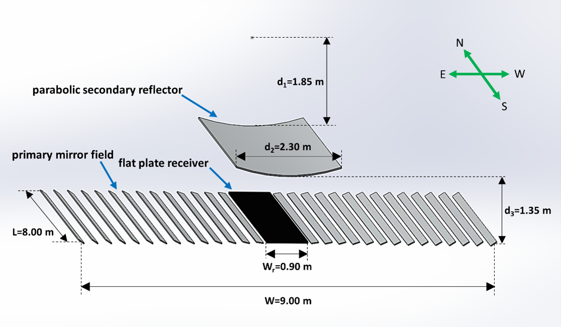
Figure 1. The examined BDLFR configuration with the parabolic secondary reflector.
Based on the parabolic profile of the hyperboloid secondary concentrator presented in section 2.2, a new, novel flat-segmented secondary concentrator is designed. The main goal of this design is to reduce even more the construction cost of the total configuration [10]. The novelty of the proposed design is that the flat concentrators are not placed at an equivalent height from the ground, but they are arranged on the parabolic profile that was presented in the previous section. Thus, this design combines the advantage of higher optical performance that the hyperboloid secondary concentrator provides compared to the flat one, and simultaneously the lower construction cost that the flat concentrators present over the hyperboloid concentrator. Additionally, the gap between the left and right sides of the flat-segmented secondary concentrator allows the direct normal irradiation to directly reach the receiver when a zero-incident angle occurs. Thus, for the hours of the day close to the solar noon, direct normal irradiation falls on the receiver without being reflected twice. To address both phenomena, the concentrated and non-concentrated solar irradiation falling upon the receiver’s surface, a specific simulation approach has been followed where the non-reflected solar rays did not suffer the reflectance losses. As a result, when both incident angles are zero, the BDLFR system with the flat-segmented secondary concentrator presents a slightly enhanced optical performance compared to the parabolic design.
In the proposed design, the number of flat segments of the flat-segmented secondary concentrator is equal to the number of primary concentrators. Each of the flat secondary concentrators is designed to symmetrically reflect the solar rays being initially reflected from their corresponding primary concentrator. More specifically, the solar rays that reach the central point of a primary concentrator, after being reflected symmetrically, are redirected towards the center of the corresponding flat secondary concentrator, and being reflected symmetrically for a second time, they reach the receiver. The furthest concentrator of the main solar field corresponds to the furthest concentrator of the flat-segmented secondary concentrator. Figure 2 presents the fundamental characteristic of the flat-segmented secondary concentrator described previously. The three design parameters of the flat concentrators are their width (Wflat), their coordinates in the x-axis (xflat) and y-axis (yflat), as well as their slope angle (ψflat). The design parameters that refer to the flat-segmented secondary concentrator are illustrated as indexed symbols in the aforementioned figure. The flat-segmented secondary concentrator’s length is equal to the solar field’s length. The first concentrator, whose index number is one, is the most distant concentrator from the solar field’s central point. The data refer only to one side of the secondary concentrator, since for the other side, the data are completely symmetrical. The thickness of every flat secondary concentrator is equal to 5.0 mm. The width of flat secondary concentrators increases as the concentrator is closer to the center of the field. Figure 3 depicts the examined BDLFR system with the flat-segmented secondary concentrator. The flat secondary concentrators do not move or rotate.
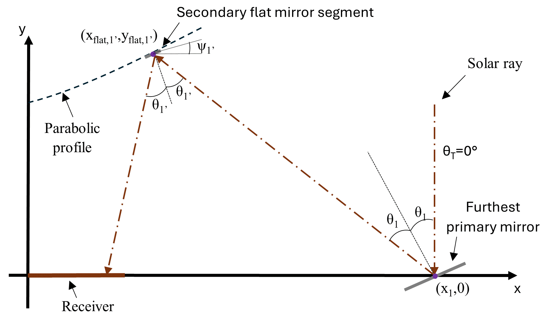
Figure 2. The one-to-one design process for the flat-segmented secondary reflector.
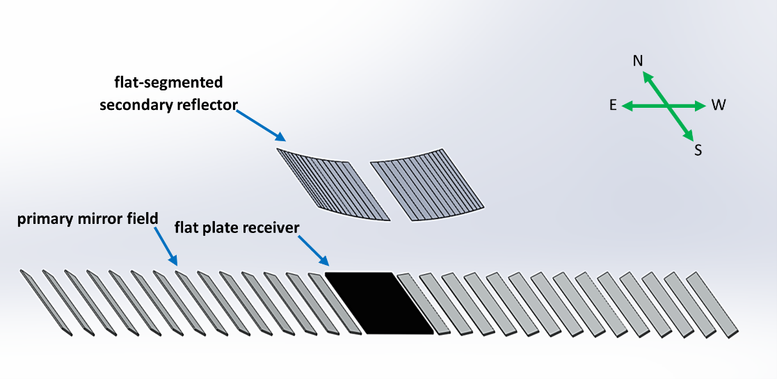
Figure 3. The examined BDLFR configuration with the flat-segmented secondary reflector.
The incident angle modifier (IAM) is a function of the optical efficiency. The optical efficiency of the BDLFR system strongly depends on the incident angle (θ). The incident angle can be distinguished into two components. The first one regards the longitudinal direction (θL), which is the incident angle’s projection on a parallel plane to the length of the solar field. The second one regards the transversal direction (θT), which is the incident angle’s projection on a parallel plane to the width of the field. The maximum optical performance occurs when both these angles’ values are zero. The IAM, which strongly depends on both these incident angles, is given by the following equation.
The intercept factor between the secondary and the primary reflectors (γ1) is computed by the following equation as the amount of solar irradiation rays that finally reach the surface of the secondary concentrator (NRsec) over the amount of solar rays that have initially fallen on the primary concentrators’ surfaces (NRprim).
The intercept factor between the receiver and the secondary concentrator (γ2) is computed as indicated in the following equation, as the amount of solar irradiation rays that manage to hit the receiver’s surface (NRr) over the amount of solar irradiation rays that have reached the secondary concentrator. It is important to clarify that the NRr refers only to the solar rays reflected from the secondary reflector. The solar rays falling directly on the receiver without being reflected first are excluded. It has to be mentioned that this methodology neglects the energy carried by each specific solar ray, which varies depending on various aspects such as the reflection losses due to imperfect reflections.
The optical performance of the total system (ηopt) is computed by multiplying the receiver’s absorptivity (αr), the reflectance of both the primary and secondary concentrators (ρprim and ρsec, respectively), the two aforementioned intercept factors (γ1 and γ2, respectively), and the incident angle modifier (IAM) based on the following equation.
However, in the present work, the optical efficiency can be computed by using the equation right below, as the quotient of the total absorbed heat flux (Qabs) and the available solar energy (Qs).
The total absorbed heat flux from the receiver is the main output from the simulation process and includes both the absorbed heat from the reflected rays due to the reflectors of the solar field and the directly absorbed heat from the direct normal irradiation falling directly on the surface of the receiver. The available solar energy (Qs) is computed by the following equation as the direct normal irradiance (Gb) multiplied by the primary concentrator field net aperture area (Aa).
The net aperture area of the primary mirror field (Aa) can be computed using the equation below, by multiplying the total primary concentrators (Nprim), their total length (L), and their width (Wprim).
Finally, it is useful to define the ratio (λ) for any parameter (i) of the flat-segmented secondary reflector against the respective parameter for the parabolic secondary reflector, as the equation below suggests, to compare the performance of these two designs for the BD reflector.
After defining the final arrangement of the primary field, an optimization procedure for the final dimensions of the parabolic secondary concentrator is conducted. The optical analysis of the parabolic design precedes the optical analysis of the flat-segmented design since the second one depends on the parabolic profile of the first one. The final shape of the secondary concentrator is one of the highly important parameters in the total design process of the BDLFR system. For the optimization procedure, both θT and θL were set to be zero, whereas the value of the solar irradiation was 1000 W/m2. These are common values for optical analysis of CSP based on the relevant literature [12]. The optimal values for the three design specifications of the parabolic secondary concentrator, which can be found in Table 1, were extracted after numerous simulations for various combinations of them. These values are the result of an optical analysis for achieving the maximum possible performance, in optical terms, for the proposed BDLFR system. After concluding their final values, an optical analysis where two of these parameters remain constant, and the third varies, is conducted. Figure 4 presents the deviation of the optical efficiency against the three design specifications of the parabolic secondary concentrator.
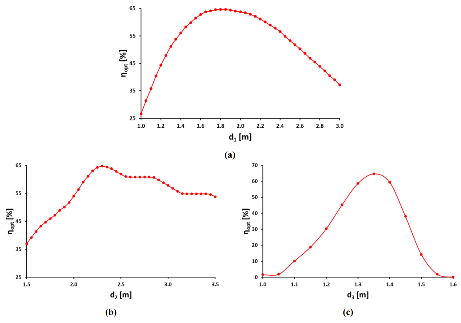
Figure 4. Optical efficiency (ηopt) against parabola’s design parameters for the parabolic secondary reflector. (a) Focal length; (b) aperture; (c) and height from the ground.
As illustrated in Figure 4, the maximum optical performance for the parabolic secondary reflector is equal to 64.7%. This value occurs when the parabola’s focal length is equal to 1.85 m, the net aperture area is equal to 2.30 m, and the parabolic secondary concentrator’s height is equal to 1.35 m. The primary mirror field’s focal length is equal to 2.0 m. Thus, a total reduction of 32.5% of the total height of the configuration in comparison with the theoretical corresponding conventional LFR system is achieved. As a result, a significant construction cost reduction is feasible, due to the fewer materials needed for the supportive equipment, as well as for the pumping system. It is also interesting to observe that, for values of the aperture width of the parabolic secondary concentrator between 2.60 m and 2.85 m, and 3.20 m and 3.45 m, the optical performance of the system does not fluctuate. Each of these is roughly equivalent to the gap between two consecutive concentrators of the primary field. This phenomenon is expected since when the aperture of the parabola increases in these ranges, it only affects the gap between two consecutive concentrators.
Figure 5 depicts (γ1), (γ2), (ηopt), and (IAM) for various values of (θT) for the parabolic secondary concentrator. It is observed that all of these factors are reduced as θL increases. When the value of θL is lower than 20°, γ1 decreases as the value of θT rises. On the contrary, if θL gets a value higher than 20°, γ1 increases as θT increases. When θL equals 20°, the γ1 remains approximately the same for every θT, and its value is 86.2%. The maximum value of γ1 is equal to 97.1%, whereas the minimum value is 47.5%. The value of γ2 increases as θT rises. The maximum value of γ2 is equal to 100%, whereas the minimum value is 38.4%. For the ηopt and the IAM, if θL is lower than 20°, then the lower the θT value, the higher their values. However, if the θL is greater than 20°, the lower the θT, the lower their values. The maximum value of ηopt is equal to 64.7%, whereas the minimum value is equal to 9.0%. The maximum value for the IAM is equal to 1.00, whereas the minimum value is equal to 0.14. It has to be mentioned that the maximum values are observed when both θT and θL are equal to zero, and the minimum values are observed when θT and θL are equal to 0° and 60°, respectively.
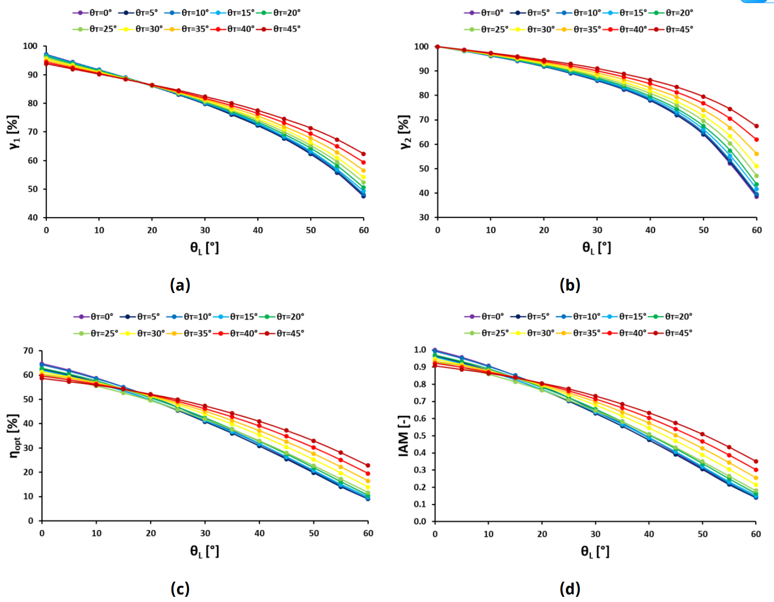
Figure 5. Optical performance indicators against (θL) for various values of (θT) for the parabolic secondary reflector; (a) intercept factor between the secondary and primary reflectors (γ1) (b) Intercept factor between the receiver and the secondary reflector (γ2); (c) optical efficiency (ηopt); (d) and incident angle modifier (IAM).
Figure 6 illustrates the same optical indicators but for the flat-segmented secondary concentrator. The same observations that occurred for the parabolic secondary concentrator also apply to the flat-segmented secondary concentrator. The maximum value of γ1 is equal to 92.3%, whereas the minimum value is equal to 45.4%. The maximum value of γ2 is equal to 100%, whereas the minimum value is equal to 37.8%. For the ηopt, the maximum value is equal to 68.5%, and the minimum value is equal to 10.8%. The optical performance is enhanced by 6.0%. Finally, for the IAM, the maximum value is equal to 1.00, whereas the minimum value is equal to 0.16. Generally, it is observed that the flat-segmented design presents a higher maximum value for optical efficiency, despite the fact that the maximum value of γ1 is higher in the parabolic design. This result is very promising since the flat-segmented design can combine optical performance and cost reduction for the BDLFR configuration. The reason that the optical performance is higher for the flat-segmented design, especially when the value of θT is small, is that direct normal irradiation directly reaches the receiver, which is not fully shaded in this design. Additionally, these solar rays do not suffer optical losses due to the double reflection from both the primary and secondary concentrators.
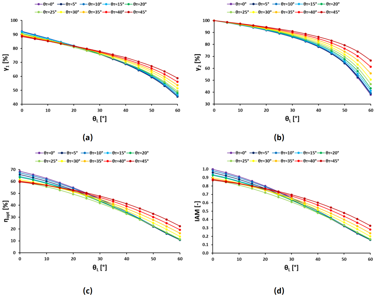
Figure 6. Optical performance indicators against (θL) for various values of (θT) for the flat-segmented secondary reflector; (a) intercept factor between the secondary and primary reflectors (γ1); (b) intercept factor between the receiver and the secondary reflector (γ2); (c) optical efficiency (ηopt); (d) and incident angle modifier (IAM).
Figure 7 depicts the variation of the ratio (λ) for all four examined optical indicators for various θT, against θL. It can be observed that the value of γ1 is lower for the flat-segmented design since the available area for reflections is reduced due to the gap between the two sides of the secondary concentrator. When the value of θL is less than 15°, the value of γ2 is approximately the same for both designs. However, there is no constant profile for the variation of γ2 for greater values of θL. For the ηopt, it is observed that if θT is less than or equal to 20°, the ηopt for the flat-segmented design is greater than for the parabolic design of the secondary concentrator. This is because solar rays directly reach the top surface of the receiver, increasing the absorbed heat. For values of θT greater than 20°, the difference is insignificant. For high values of θT and θL, the ηopt of the parabolic design is slightly higher, but the difference is too small to be considered. For the IAM, when the value of θT is equal to or greater than 20°, the IAM for the parabolic contour is higher than the IAM for the flat-segmented shape. For lower values of θT, the greater the θL, the value of IAM is enhanced for the flat-segmented design compared to the parabolic one.
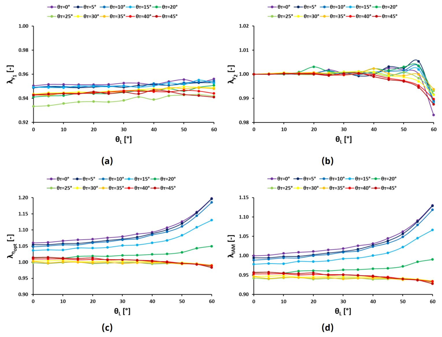
Figure 7. Ratio (λ) of the intercept factor between the secondary and primary reflectors (γ1). (a) intercept factor between the receiver and the secondary reflector (γ2); (b) optical efficiency (ηopt); (c) and incident angle modifier (IAM); (d) against the (θL) for various values of (θT) for the parabolic secondary reflector compared to the flat-segmented secondary reflector.
Figure 8 depicts the heat flux distribution on the absorptance plate of the receiver for both incident angles equal to zero. Some of the primary mirrors are not shown for the convenience of the reader, so that the color scale is easier to read. The maximum heat flux for the parabolic secondary concentrator is 25888 W/m2, while the maximum heat flux for the flat-segmented secondary concentrator is 21982 W/m2. This means that, since the total absorbed heat is greater for the flat-segmented design, the heat flux is more evenly distributed on the surface of the absorber. As a result, there are fewer hot spots on the surface of the receiver, which reduces the thermal stresses and increases the reliability of the receiver, and consequently the system.
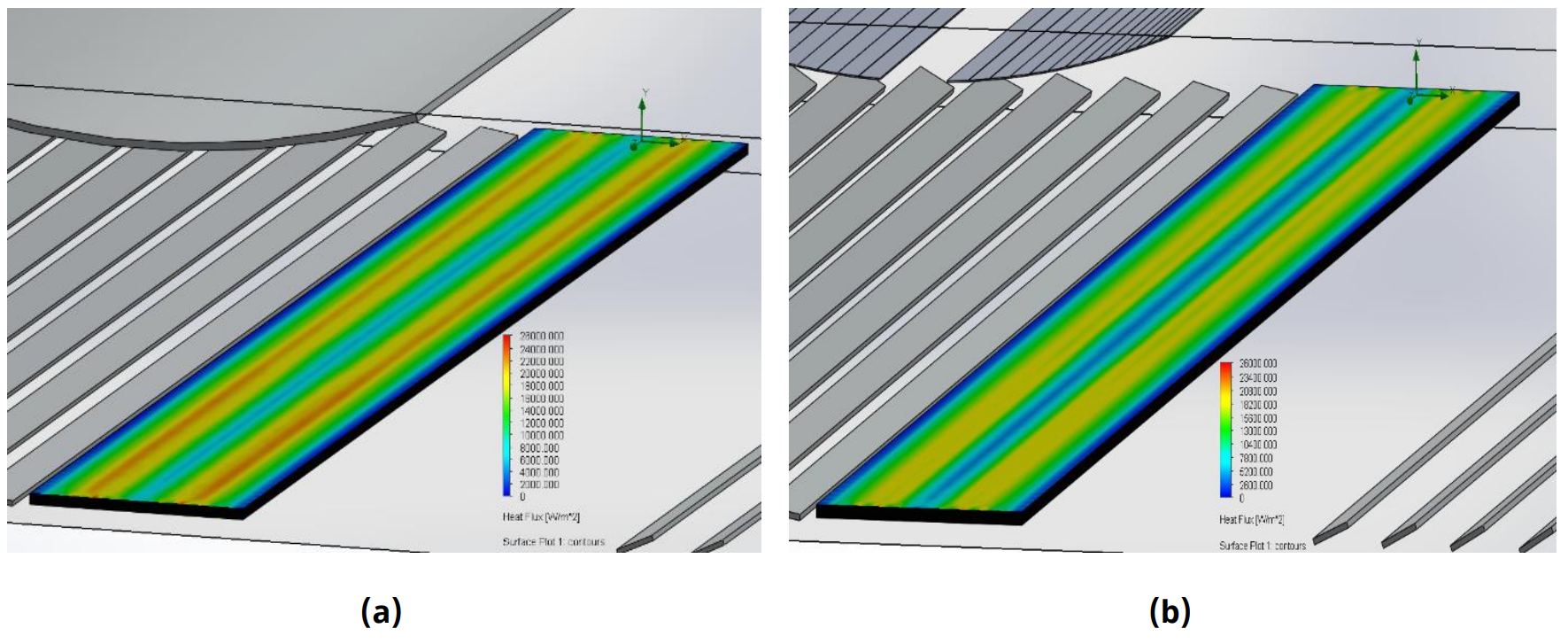
Figure 8. Heat flux distribution on the surface of the receiver for (a) the parabolic and (b) the flat-segmented secondary reflector. Note: Some primary mirrors are hidden for a clearer illustration of the contour’s color scale.
In this work, a BDLFR system is investigated in optical terms. Two different secondary concentrators coupled with a flat plate receiver are examined, a parabolic and a flat-segmented. For the parabolic secondary concentrator, the maximum γ1 is 97.1%, the maximum γ2 is 100%, the maximum IAM is 1.0, and the maximum ηopt is 64.7% when both θT and θL are equal to zero. The minimum γ1 is 47.5%, the minimum γ2 is 38.4%, the minimum IAM is 0.14, and the minimum ηopt is 9.0% when θT is equal to zero, and θL is equal to 60°. For the flat-segmented secondary concentrator, the maximum γ1 is 92.3%, the maximum γ2 is 100%, the maximum IAM is 1.0, and the maximum ηopt is 68.6% when both θT and θL are equal to zero. The minimum γ1 is 45.4%, the minimum γ2 is 37.8%, the minimum IAM is 0.16, and the minimum ηopt is 10.8% when θT is equal to zero, and θL is equal to 60°. The γ1 of the flat-segmented design is less compared to that of the parabolic design for every incident angle. This is because of the existing gap between the two sides of the flat-segmented concentrator, which reduces the available area for the reflected solar rays to reach its surface. However, this gap is beneficial for the overall optical performance of the proposed system. The γ2 of the parabolic design is approximately the same as γ2 of the flat-segmented design. This is because the flat secondary concentrators are arranged based on the profile of the parabolic design, whose profile was designed to ensure the maximum possible concentration of solar irradiation rays on the absorptive receiver’s surface, aiming to increase the maximum optical performance. When θL is less than 15°, γ1 is approximately the same for both designs. For greater values of θL, there is not a direct correlation between γ1 of these two designs. The IAM of the parabolic design is higher than that of the flat-segmented design when θT is greater than 20°. For θT less than or equal to 10° and θL greater than 20°, the IAM of the flat-segmented design is better than that of the parabolic design. As can be seen, the optical efficiency of the flat-segmented design is better, considering the overall optical efficiency, although it has a lower performance considering the rest of the optical evaluation indexes. This is because, for small incident angles, an important quantity of solar rays directly reaches the absorptive surface of the receiver without suffering from reflective optical losses. It is observed that for lower θT values and for higher θL values, the enhancement in the optical performance of the flat-segmented design improves more over the parabolic one. The optical performance of the parabolic design overcomes that of the flat-segmented design only for very high incident angle values. As a result, the optical performance of the flat-segmented design is better. It has to be mentioned that this study does not address the extra shading losses added to the system because of the supportive structure. Also, the misalignment issue while placing the secondary reflector is equally important as for the mirrors of the primary field, and special attention must be given. Regarding the overall construction cost of the secondary reflector, it is obvious that the construction of the flat-segmented reflector is significantly lower compared to the parabolic. This is because flat metal sheets are easy to find on the market, and do not require excessive mechanical processes for modifying their shape, which are expensive, especially if high accuracy is mandatory. However, the construction of the supportive structure is more likely to be of higher cost for the flat-segmented due to the need to add extra supportive elements.
In this work, a novel BDLFR system is proposed, and the optical analysis of this system is conducted, intending to calculate the intercept factors, the optical performance, and the IAM variation for various values of the incident angles in both the longitudinal and the transversal direction. Firstly, a parabolic secondary concentrator is proposed and analyzed. Based on the parabolic profile, a new novel flat-segmented secondary concentrator is being proposed, aiming to further reduce the construction cost of the system. The most crucial conclusions of this work are listed below:
The BDLFR system presents a lower total height in comparison with the respective theoretical LFR for the same main solar field. The reduction of the total height of the proposed system was estimated at 32.5%, which reduces the materials needed for the supportive equipment and the pumping system.
The (ηopt,max) of the flat-segmented design is equal to 68.6%. Compared to the corresponding maximum value for the parabolic design, this value is 6.0% enhanced.
The heat flux is more evenly distributed on the receiver’s surface when the flat-segmented secondary concentrator is diploid. Thus, the thermal stresses are reduced, and the reliability of the system is increased.
For future study, a thermal analysis has to be conducted since the optical analysis alone presents some limitations, such as neglecting the thermal losses, which are crucial for CSP. A thermal analysis, including a computational fluid dynamics analysis for the receiver to calculate conduction, convection, and radiation losses, will allow the calculation of the thermal performance of the system. Also, a technoeconomic analysis of both proposed configurations could be useful to estimate the exact cost reduction between the LFR and the BDLFR systems, as well as between the parabolic and the flat-segmented secondary concentrator.
Data will be made available by the authors on request.
The first author would like to thank the “Cyprus State Scholarship Foundation” for its financial support.
The authors have declared that no competing interests exist.
Conceptualization: C.S. and E.B.; Methodology: C.S. and E.B.; Software: C.S., E.B. and D.K.; Validation: C.S., E.B. and D.N.K.; Formal Analysis: C.S.; Investigation: C.S., A.K. and E.B.; Resources: E.B. and C.T.; Data Curation: C.S., P.L. and E.V.; Writing – Original Draft: C.S.; Writing – Review & Editing: E.B., A.K., P.L. and C.T.; Visualization: C.S., E.B. and D.G.; Supervision: E.B. and C.T.; Project Administration: C.T.; Funding Acquisition: C.S. and C.T.
| 1. | Jaworski S, Chrzanowska M, Zielińska-Sitkiewicz M, Pietrzykowski R, Jezierska-Thöle A, Zielonka P. Evaluating the Progress of Renewable Energy Sources in Poland: A Multidimensional Analysis. Energies. 2023;16(18):6431. [Google Scholar] [CrossRef] |
| 2. | Miglioli A, Aste N, Del Pero C, Leonforte F. Photovoltaic-thermal solar-assisted heat pump systems for building applications: Integration and design methods. Energy Built Environ. 2023;4(1):39-56. [Google Scholar] [CrossRef] |
| 3. | Schoeneberger CA, McMillan CA, Kurup P, Akar S, Margolis R, Masanet E. Solar for industrial process heat: A review of technologies, analysis approaches, and potential applications in the United States. Energy. 2020;206:118083. [Google Scholar] [CrossRef] |
| 4. | Khan J, Arsalan MH. Solar power technologies for sustainable electricity generation – A review. Renew Sustain Energy Rev. 2016;55:414-425. [Google Scholar] [CrossRef] |
| 5. | Marefati M, Mehrpooya M, Shafii MB. Optical and thermal analysis of a parabolic trough solar collector for production of thermal energy in different climates in Iran with comparison between the conventional nanofluids. J Clean Prod. 2018;175:294-313. [Google Scholar] [CrossRef] |
| 6. | Shahabuddin M, Alim MA, Alam T, Mofijur M, Ahmed SF, Perkins G. A critical review on the development and challenges of concentrated solar power technologies. Sustain Energy Technol Assess. 2021;47:101434. [Google Scholar] [CrossRef] |
| 7. | Bellos E. Progress in beam-down solar concentrating systems. Prog Energy Combust Sci. 2023;97:101085. [Google Scholar] [CrossRef] |
| 8. | Xu H, Xu C, Li S, Zhang Z, Liu Y, Xin T, et al. A beam-down solar concentrator with a fixed focus — Design and performance analysis. Sol Energy. 2022;241:428-436. [Google Scholar] [CrossRef] |
| 9. | Mokhtar M, Meyers SA, Armstrong PR, Chiesa M. Performance of a 100 kWth Concentrated Solar Beam-Down Optical Experiment. J Sol Energy Eng. 2014;136(4):041007. [Google Scholar] [CrossRef] |
| 10. | Taramona S, González-Gómez PÁ, Briongos JV, Gómez-Hernández J. Designing a flat beam-down linear Fresnel reflector. Renew Energy. 2022;187:484-499. [Google Scholar] [CrossRef] |
| 11. | Matsson JE. An introduction to Solidworks® flow simulation 2019. Mission, KS, USA: SDC Publications; 2019. |
| 12. | Bellos E, Tzivanidis C, Papadopoulos A. Secondary concentrator optimization of a linear Fresnel reflector using Bezier polynomial parametrization. Sol Energy. 2018;171:716-727. [Google Scholar] [CrossRef] |
| 13. | Taramona S, Gallo A, González-Camarillo H, Minio Paluello G, Briongos JV, Gómez-Hernández J. Beam-down linear Fresnel reflector prototype: Construction and first tests. Renew Energy. 2024;220:119697. [Google Scholar] [CrossRef] |
| 14. | Khandelwal N, Sharma M, Singh O, Shukla AK. Comparative evaluation of Integrated Solar combined cycle plant with cascade thermal storage system for different heat transfer fluids. J Clean Prod. 2022;353:131519. [Google Scholar] [CrossRef] |

![]()
Copyright © 2026 Pivot Science Publications Corp. - unless otherwise stated | Terms and Conditions | Privacy Policy


